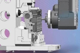
Not every problem can be solved with a quick glance into the machine. This is because there are often correlations and interactions between different parameters, which can only be discovered with a comprehensive analysis of the machining process. Gühring offers precisely this with its detailed process data analysis service. Our experienced machining experts develop solutions using the data obtained. As a result, hidden problems and potential improvements no longer remain a mystery.
How does process data analysis work?
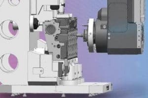
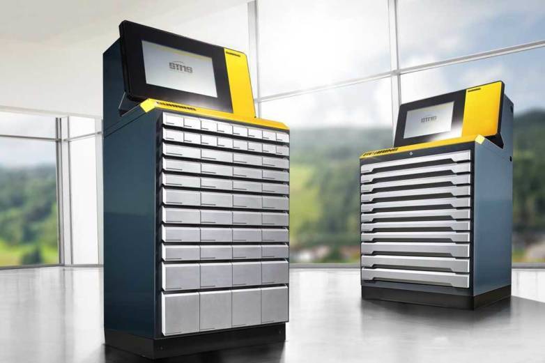
With the help of our process data recordingtool, we collect all factors that affect the tool, clamping and workpiece directly from your machine. This performance data is then evaluated and graphically displayed in the Tool Management Software (GTMS). This approach enables us to gain a reliable database for error analysis and process optimisation by our experts.
The following parameters can be evaluated:
- Drops in performance (recognisable based on feed curves)
- Machine-side problems (calibration with override is possible)
- Power consumption of all axes and spindles in watts
- Position data for all axes
- Error messages from the NC program
- Secondary and main times
- Program code for corresponding visualisation
Here are three examples of successful process data analysis:
Problem 1: High degree of wear in deep hole drilling
Problem: When drilling deep holes in crankshafts, a customer complains of poor service life and occasionally even tool breakage. The surfaces of the components also do not meet the quality requirements.
Analysis: In order to find out what factors affect the tool and process, the Gühring experts tested two tools with different geometries and looked at the spindle utilisation rate. While this progresses evenly with the optimised tool (blue line), extreme fluctuations are noticeable with the previously deep hole drill used (red line). When taking a closer look at the tool, it also becomes clear why this happened: Its rough surfaces impair chip removal. This increases friction during drilling and therefore increases wear.
Solution: Since reliable chip removal is of fundamental importance for deep hole drilling, the customer is recommended a special tool with optimised surface quality and modified coating. This tool performs significantly better – and, most importantly, for longer.
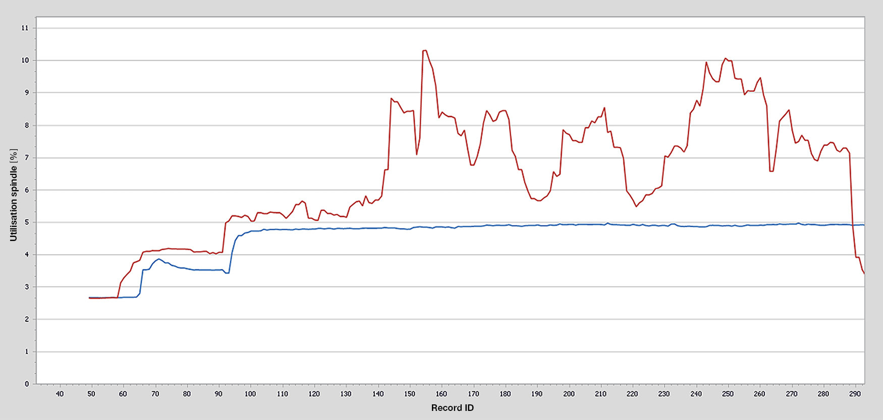
Deep hole drill 1 (blue line, Ø 8 mm) achieves a vc of 90 m/min, with a max. load on the axis of 4.95 %. For the same vc, the axial load for deep hole drill 2 (red line, Ø 8 mm) is max. 10.30 %.
All feed charts were filtered to ± 250 mm/min.
Problem 2: Breakage of micro tools
Problem: A customer is carrying out drilling tests in stainless steel (V4A). The micro tool with a diameter of 1.25 mm keeps breaking off. Because the reasons for this could not be discovered in the traditional way, Gühring planned to use process data analysis to find out why the tools are breaking.
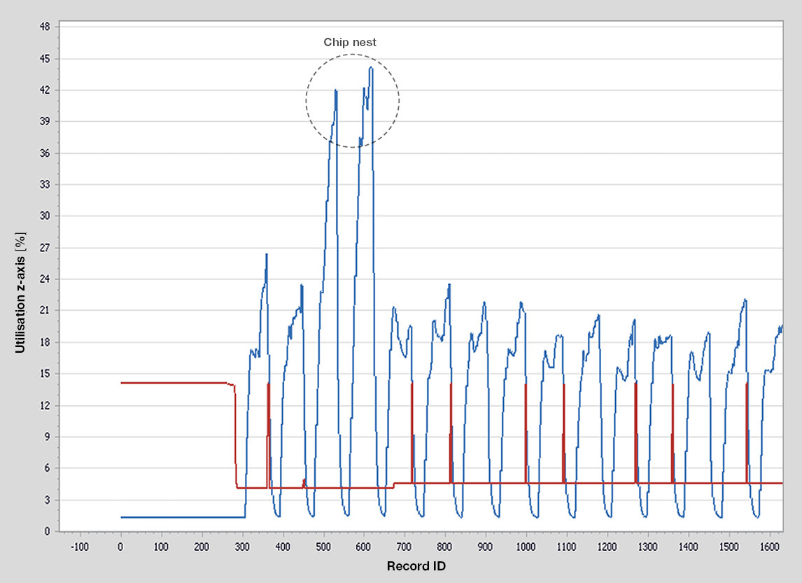
Analysis: Analysis of the spindle utilisation gives a clear picture: After just two holes, the spindle power suddenly doubles and then normalises again. Thanks to their many years of experience, Gühring experts immediately knew what caused these blips. Due to poor chip evacuation, chip nests had formed during the drilling process. In many cases, these chip nests loosened again after a few holes, but not always. They then caused the delicate micro drills to break.
Solution: In order to optimise chip removal, Gühring recommends using a design with a coated tool surface instead of the bare tool. The coating minimises friction during drilling and prevents built up edge.
With a drill (Ø 1.25 mm, vc = 15 m/min), it can be seen that the spindle utilisation (blue line) doubles abpruptly with the same feed rate (red line, 57 mm/min). This indicates that chip jams generate more radial than axial forces.
Problem 3: Concentricity problems when reaming
Problem: When pre-machining a motor component with a reamer, concentricity problems keep occurring – without the reason being apparent from the outside. The diameter of the hole is enlarged in these components.
Analysis: The entire process including pre-machining is observed over a long period of time. The result: While most drilling operations are completed normally, experts identify jumps in the axial load with hole no. 4. Here, the load rises sharply when compared with the other holes. The reason was easy to find: Chips must have entered the hole during pre-machining. In most cases, these were pushed through the hole during machining. However, in the case of the fourth hole, a chip jams in the reamer and pushes it out, which led to the expansion.
Solution: The problem was easily solved with an additional swivel of the A-axis.
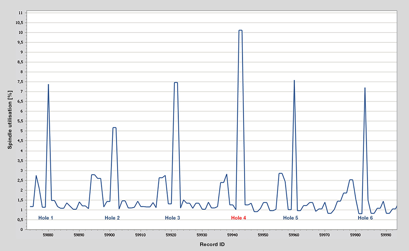
When machining with Ø 10H7, the tool generates a max. spindle load of 2.8 %. At Ø 28.1, the spindle load increases to 10.1 % and normalises again for the following holes.
Have we piqued your interest?
You can find out about our new “process data analysis” service here.
Or arrange your consultation appointment now:
Technical advice and support are also available quickly and directly via our service hotline 00800 2607 2607. We can also be reached on WhatsApp: +49 172 658 53 53. Save the number!
You might also be interested in:
Conserving resources for the future: 5 reasons for carbide recycling
Save resources and benefit from carbide recycling with Gühring! Exchange worn tools for money and reduce your carbon footprint. Simple, sustainable and efficient.
Tool management in flux: Keeping track with digital tech
Getsch+Hiller optimiert mit der Gühring Tool Management Software (GTMS) seine Werkzeugverwaltung. Dank digitaler Ausgabeschränke und modularer Software spart das Unternehmen Zeit, reduziert Kosten und bleibt flexibel – perfekt angepasst an das schnelle Wachstum der Medizintechnik.
Detailed data on your tools: The GTMS tool data module
Increase your efficiency with the GTMS tool data module. Avoid sources of error, optimise set-up times and gain full transparency over tool requirements and component costs. Experience precise tool data management for maximum control.

