


Komplizierte Tiefbohrung
Mit dieser Strategie gelingt die Querbohrung mit dem Tieflochbohrer
Tiefbohrbearbeitungen fallen häufig im Formenbau sowie in zahlreichen anderen Branchen an. Doch immer wieder ist es dabei von konstruktiver Seite vorgegeben, dass sich zwei Bohrungen kreuzen. Solche sich kreuzenden Tiefbohrungen lassen sich also nicht vermeiden, doch ihre Bearbeitung ist knifflig: Denn in dem Moment, in dem der Tieflochbohrer aus der einen Bohrung austritt und in die nächste eintritt, durchquert er einen Lückenbereich, in dem der Kühlprozess unterbrochen wird und eine teils sehr ungünstige Anbohr- bzw Führungssituation entsteht. Das Kühlmittel ist nicht mehr imstande die entstehenden Späne ordentlich auszuspülen, die das Werkzeug beschädigen können. Auch die Führung des Werkzeugs ist unterbrochen, worunter die Stabilität des Werkzeugs nicht mehr gegeben ist. Nur mit der richtigen Strategie und dem geeigneten Werkzeug kann ein solcher Lückenbereich prozesssicher überbrückt werden.

Vorgehen bei Lückenbereichen

Bauteil bereitgestellt von der Tebis AG
Das richtige Vorgehen bei Querbohrungen zeigen wir anhand eines Praxisbeispiels: In eine Formplatte aus Stahl (1.2321) muss eine Vielzahl an Tieflochbohrungen eingebracht werden. Diese dienen später als Temperierbohrungen, durch die ein Kühlmittel fließt, um die Temperatur der Form zu kontrollieren. Hergestellt werden diese Bohrungen auf einem horizontalen Bearbeitungszentrum von DMG, die Programmierung erfolgte über Tebis. Doch Querbohrungen und die dadurch entstehenden Lückenbereiche machen die Bearbeitung besonders anspruchsvoll. Hier unterscheiden wir zwei Bohrsituationen, bei denen sich jeweils ein bestimmtes Vorgehen bewährt hat.
Zwei Bohrungen treffen sich im 90°-Winkel
Nicht jede Querbohrung ist problematisch: Treffen zwei Bohrungen in einem 90°-Winkel aufeinander, läuft die Bearbeitung meistens reibungslos ab. In solchen Fällen hat sich ein bestimmtes Vorgehen bewährt, das wir am nachfolgenden Beispiel skizzieren.
Tieflochbohren einer Querbohrung als Sackloch in Stahl

- Wir fahren im Linkslauf mit einem reduzierten Vorschubgeschwindigkeit von 30 mm/min und einer Drehzal von 500 U/min in die Pilotbohrung ein. Geführt wird das Werkzeug beim Einfädeln durch die Pilotbohrung mit 12 mm Tiefe.
- Sobald sich der Bohrer in der Bohrung befindet, wird die Vorschubgeschwindigkeit erhöht auf 60 mm/min und mit diesem erhöhten Bohrvorschub bis zur Querbohrung gebohrt.
- Wir treten mit dem gleichen hohen Vorschub in die Querbohrung ein und erst bei Wiedereintritt in die zweite Bohrung reduzieren wir den die Vorschubgeschwindigkeit um die Hälfte von 60 auf 30 mm/min.
- Nach dem Einfädeln in die zweite Bohrung erhöhen wir den Vorschub erneut auf 60 mm/min und bohren die Bohrung mit diesem hohen Vorschub zu Ende.
| Werkzeug | Einlippen-Tieflochbohrer EB 80, ⌀ 8 mm |
|---|---|
| Bauteil | Formplatte |
| Material | Stahl (1.2321) |
| Schnittgeschwindigkeit | Vc = 50 m/min |
| Drehzahl | n = 1990 U/min |
| Vorschubgeschwindigkeit | Vf = 60 mm/min |
| Bohrtiefe | ap = 320 mm |
| Standwegerwartung | 10 m/175 min = 32 Bauteile |
| Gesamtzeit Bohrung | 332 sek |
| Zeitspanvolumen | 3cm³/min |
Zwei Bohrungen bilden einen kritischen Lückenbereich
Schwieriger wird es, wenn die Kreuzung zwischen den Bohrungen von diesem 90°-Winkel abweicht (s. untere Querbohrung in der Grafik). Auch wenn eine kleine auf eine größere Bohrung trifft (s. obere Querbohrung in der Grafik) entstehen Probleme.

5 Regeln für perfekte Querbohrungen

- kleine Durchmesser vor großen Durchmessern
- tiefe Bohrungen vor kurzen Bohrungen
- Lückenbereiche vermeiden (Druckverlust des Kühlmittels)
- Lückenbereiche, wenn möglich, mit kurzen Bohrern bearbeiten (Torsion)
- Querbohrungen verschließen um Druckverlust und Spanumleitung zu vermeiden
Technische Beratung und Support erhalten Sie auch schnell und direkt über unsere Service-Hotline 00800 2607 2607.
Auch auf WhatsApp sind wir für Sie erreichbar: +49 172 658 53 53. Gleich einspeichern!
VA-Gewinde problemlos meistern
Rückbau von Atomkraftwerken verlangt Präzision – besonders bei VA-Gewinden. Weisser Bärwinkel setzt auf den Pionex von Gühring und meistert selbst zähe Edelstähle sicher. Ergebnis: stabilere Prozesse, längere Standzeiten und höhere Produktivität.
Gewindebohrer für die Energiebranche
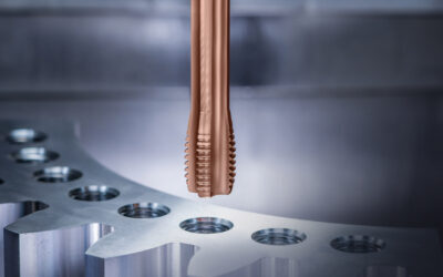
Die Gewindefertigung in der Energiebranche stellt höchste Anforderungen an Präzision und Prozesssicherheit. Mit dem Gühring Hochleistungsgewindebohrer Energy steht ein Branchenspezialist bereit, der anspruchsvolle Gewinde fertigt.
Modularer Gewindeformer beim Kranbau
Eine Innovation – der neue modulare Gewindeformer von Gühring – hat es ermöglicht, tief liegende Herausforderungen in der Herstellung von Sacklochgewinden bei Karl Georg zu lösen und die Prozesssicherheit auf ein neues Niveau zu heben.